Overload Protection for Electric Motors
Thermal images are an easy way to identify apparent temperature differences in industrial three-phase electrical circuits, compared to their normal operating conditions. By inspecting the thermal differences of all three phases side-by-side, technicians can quickly spot performance anomalies on individual legs due to unbalance or overloading.
Electrical unbalance is generally caused by differing phase loads but may also be due to equipment issues such as high resistance connections. A relatively small unbalance of the voltage supplied to a motor will cause a much larger current unbalance which will generate additional heat and reduce torque and efficiency. A severe unbalance can blow a fuse or trip a breaker causing single phasing and the problems associated with it such as motor heating and damage.
In practice, it is virtually impossible to perfectly balance the voltages across three phases. To help equipment operators determine acceptable levels of unbalance, the National Electrical
Manufacturers Association (NEMA) has drafted specifications for different devices. These baselines are a useful point of comparison during maintenance and troubleshooting.
What to check?
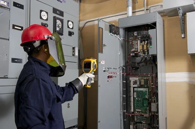
Capture thermal images of all electrical panels and other high load connection points such as drives, disconnects, controls and so on. Where you discover higher temperatures, follow that circuit and examine associated branches and loads.
Check panels and other connections with the covers off. Ideally, you should check electrical devices when they are fully warmed up and at steady state conditions with at least 40 percent of the typical load. That way, measurements can be properly evaluated and compared to normal operating conditions.
What to look for?
Equal load should equate to equal temperatures. In an unbalanced load situation, the more heavily loaded phase(s) will appear warmer than the others, due to the heat generated by resistance. However, an unbalanced load, an overload, a bad connection, and a harmonic issue can all create a similar pattern. Measuring the electrical load is required to diagnose the problem.
A cooler-than-normal circuit or leg might signal a failed component.
It is sound procedure to create a regular inspection route that includes all key electrical connections. Using the software that comes with the thermal imager, save each image you capture on a computer and track your measurements over time. That way, you’ll have baseline images to compare to later images. This procedure will help you determine whether a hot or cool spot is unusual. Following corrective action, new images will help you determine if repairs were successful.
What represents a “red alert?”
Repairs should be prioritized by safety first—i.e., equipment conditions that pose a safety risk—followed by criticality of the equipment and the extent of the temperature rise. NETA (InterNational Electrical
Testing Association) guidelines suggest that temperatures as small as 1°C above ambient and 1°C higher than similar equipment with similar loading could indicate a possible deficiency that warrants investigation.
NEMA standards (NEMA MG1-12.45) warn against operating any motor at a voltage unbalance exceeding one percent. In fact, NEMA recommends that motors be derated if operating at a higher unbalance. Safe unbalance percentages vary for other equipment.
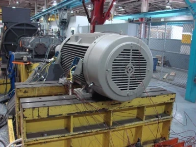
Motor failure is a common result of voltage unbalance. Total cost combines the cost of a motor, the labour required to change out a motor, the cost of product discarded due to uneven production, line operation and the revenue lost during the time a line is down.
Follow-up actions
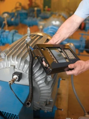
When a thermal image shows an entire conductor is warmer than other components throughout part of a circuit, the conductor could be undersized or overloaded. Check the conductor rating and the actual load to determine which is the case. Use a multimeter with a clamp accessory, a clamp meter or a power quality analyzer to check current balance and loading on each phase.
On the voltage side, check the protection and switchgear for voltage drops. In general, line voltage should be within 10 % of the nameplate rating. Neutral to ground voltage can be an indication of how heavily your system is loaded or may be an indication of harmonic current. Neutral to ground voltage higher than 3 % of nominal voltage should trigger further investigation. Also consider that loads do change, and a phase can suddenly be significantly lower if a large single-phase load comes online.
Voltage drops across the fuses and switches can also show up as unbalance at the motor and excess heat at the root trouble spot. Before you assume the cause has been found, double check with both the thermal imager and multi-meter or clamp meter current measurements. Neither feeder nor branch circuits should be loaded to the maximum allowable limit.
Circuit load equations should also allow for harmonics. The most common solution to overloading is to redistribute loads among the circuits, or to manage when loads come on during the process.
Using the associated software, each suspected problem uncovered with a thermal imager can be documented in a report that includes a thermal image and a digital image of the equipment. That’s the best way to communicate problems and to suggest repairs.
Colin Plastow has been with Fluke Electronics Canada since 1987 in various support and product management positions.